Earlier this summer, I worked on a tiny piece of the Embrace sculpture, for Burning Man 2014.

Inside were 2 hearts, one made here in Portland by Lostmachine Andy & other burners at Flat Rat Studios. I made electronics to gradually fade 4 incandescent light bulbs in heart beating patterns.
Click "Read more" for technical details and many more wonderful photos (taken by Sarah Taylor)....

Inside the enormous sculpture were two hearts. The blue on was built by a group in Vancouver, B.C., Canada, and of course this one was built here in Portland, Oregon, USA.

Andy wanted this heart to have a very warm, gentle atmosphere, with warn incandescent bulbs slowly fading to create the heart beat. These effect turned out quite well.

Here's a quick video, from the first test of the light controller.
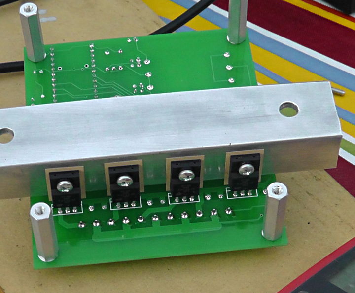
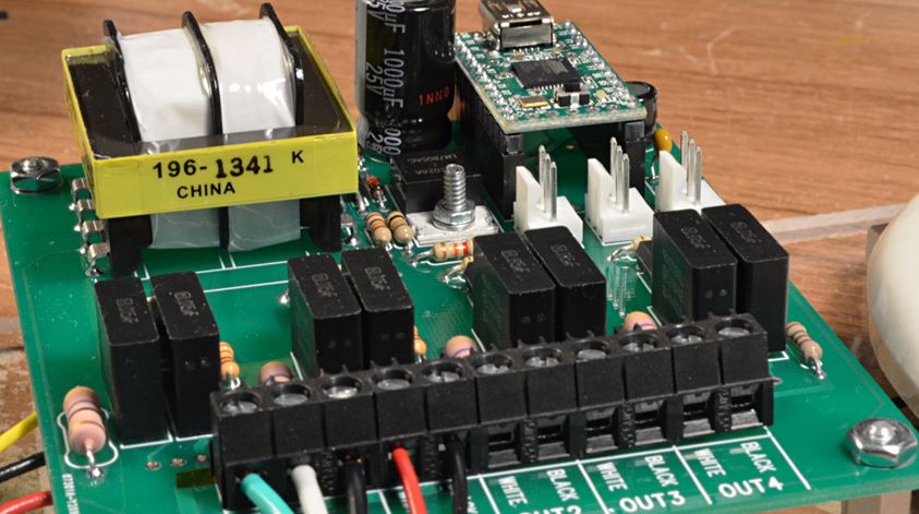
The electronics all fit onto this circuit board, which is approximately 4 by 3.5 inches.
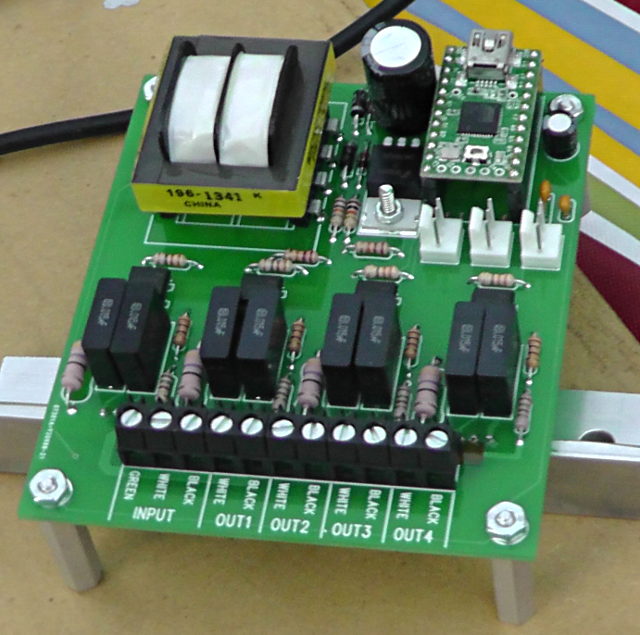
The four BT139X Triacs that actually switch the AC voltage are mounted on the bottom side to a heatsink that's meant to dissipate any heat to the metal case. Originally Andy believed the lights might be 500 watts each, so I was concerned about heat. In the end, four 60 watt bulbs were used and the Triacs did not get noticeably warm.
Here is a parts placement diagram for building the circuit board. Two boards were built, the one that ran the project and a spare... just in case!
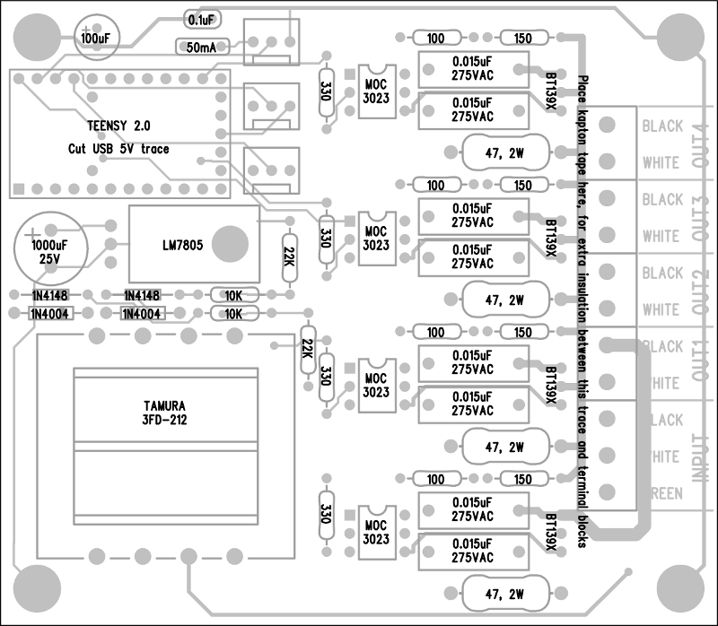
The PCB cad files are attached below, if anyone wants to make more of these boards.

The AC switching circuitry was basically Fairchild Semiconductor's recommended circuit for the MOC3023 optical isolator, which allows a Teensy 2.0 board to safely control the AC voltage. Four copies of this circuit were built on the board.
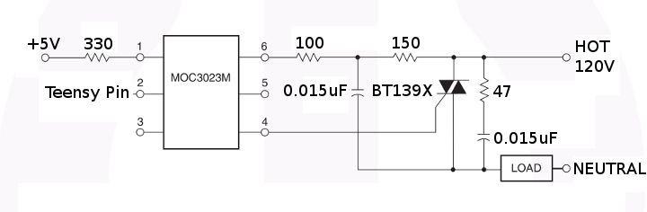
This circuit requires the Teensy 2.0 to know the AC voltage timing, so it can trigger the Triac at the right moment. Triggering early in the AC waveform causes the Triac to conduct near the full AC voltage for maximum brightness. Triggering later reduces the brightness.
To get the AC timing, I built this special power supply onto the board.
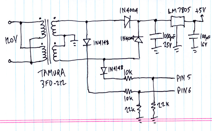
The Teensy 2.0 receives pulses on pins 5 and 6 as the AC waveform cycles positive and negative.
One caveat is this approach depends on the AC voltage being a sine wave. The AC voltage was one of the first questions I asked Andy, and he was told Burning Man would supply a true sine wave AC voltage. When he got out there, it turned out the power was actually a "modified sine wave", which really isn't anything like a sine wave. This circuit didn't work well. Fortunately, they were able to run the lighting from a small generator that produced a true sine wave.

With the AC timing arriving on pins 5 and 6, and 4 pins able to trigger Triacs, and 3 pins connected to analog voltages for changing speed, brightness and pattern, the only other major piece of this technology puzzle is the software.
In this code, loop() tracks the changes in the waveform on pins 5 & 6, and it fires the Triacs at their programmed times. 120 times per second (each AC half cycle), the recompute_levels() function runs, which reads the analog controls and changes the Triac time targets, which loop() uses to actually control the voltage outputs.
Here's all the code:
void setup()
{
	pinMode(0, INPUT_PULLUP);	// unused
	pinMode(1, INPUT_PULLUP);	// unused
	pinMode(2, INPUT_PULLUP);	// unused
	pinMode(3, INPUT_PULLUP);	// unused
	pinMode(4, INPUT_PULLUP);	// unused
	pinMode(5, INPUT);		// Phase A
	pinMode(6, INPUT);		// Phase B
	pinMode(7, INPUT_PULLUP);	// unused
	pinMode(8, INPUT_PULLUP);	// unused
	pinMode(9, INPUT_PULLUP);	// unused
	pinMode(10, INPUT_PULLUP);	// unused
	digitalWrite(11, LOW);
	pinMode(11, OUTPUT);		// LED
	digitalWrite(12, HIGH);
	pinMode(12, OUTPUT);		// trigger4, low=trigger
	digitalWrite(13, HIGH);
	pinMode(13, OUTPUT);		// trigger3, low=trigger
	digitalWrite(14, HIGH);
	pinMode(14, OUTPUT);		// trigger2, low=trigger
	digitalWrite(15, HIGH);
	pinMode(15, OUTPUT);		// trigger1, low=trigger
	pinMode(16, INPUT_PULLUP);	// unused
	pinMode(17, INPUT_PULLUP);	// unused
	pinMode(18, INPUT_PULLUP);	// unused
	analogRead(19);			// pot #3
	analogRead(20);			// pot #2
	analogRead(21);			// pot #1
	pinMode(22, INPUT_PULLUP);	// unused
	pinMode(23, INPUT_PULLUP);	// unused
	pinMode(24, INPUT_PULLUP);	// unused
}


uint8_t pot1=0, pot2=0, pot3=0;
uint8_t level1=100, level2=128, level3=0, level4=250;


uint8_t phase_to_level(uint16_t phase)
{
	uint16_t amplitude;

	// 10923 = 32768 / 3
	//     0 to 10922 = increasing: 0 -> 32767
	// 10923 to 21845 = decreasing: 32767 -> 0
	// 21846 to 32768 = increasing: 0 -> 32767
	// 32769 to 43691 = decreasing: 32767 -> 0
	// 43692 to 65535 = resting: 0

	if (phase < 10923) {
		amplitude = phase * 3;
	} else if (phase < 21845) {
		phase = phase - 10923;
		phase = 10922 - phase;
		amplitude = phase * 3;
	} else if (phase < 32768) {
		phase = phase - 21846;
		amplitude = phase * 3;
	} else if (phase < 43691) {
		phase = phase - 32769;
		phase = 10922 - phase;
		amplitude = phase * 3;
	} else {
		amplitude = 0;
	}
	//amplitude = (phase < 32768) ? phase : 65535 - phase;
	amplitude >>= 6;  // range 0 to 511
	amplitude *= (pot2 + 84) / 6;  //
	amplitude += 6000 + pot2 * 8; // minimum brightness
	return (amplitude < 32768) ? amplitude >> 7 : 255;
}

void recompute_levels()
{
	static uint16_t phase=0;
	static uint8_t n=0;

	analog_update();
	//Serial.print("pot: ");
	//Serial.print(pot1);
	//Serial.print(", ");
	//Serial.print(pot2);
	//Serial.print(", ");
	//Serial.print(pot3);
	phase += (((uint16_t)pot1 * 83) >> 5) + 170;
	//Serial.print(", phase: ");
	//Serial.print(phase);
	if (pot3 < 128) {
		level1 = phase_to_level(phase);
		level2 = level1;
		level3 = phase_to_level(phase + pot3 * 52);
		level4 = level3;
	} else {
		uint16_t n = (pot3 - 127) * 26;
		level1 = phase_to_level(phase);
		level2 = phase_to_level(phase + 6604 - n);
		level3 = phase_to_level(phase + 6604);
		level4 = phase_to_level(phase + 6604 + n);
	}
	//Serial.print(", levels: ");
	//Serial.print(level1);
	//Serial.print(", ");
	//Serial.print(level2);
	//Serial.print(", ");
	//Serial.print(level3);
	//Serial.print(", ");
	//Serial.print(level4);
	//Serial.println();
}


void loop()
{
	uint8_t a, b, prev_a=0, prev_b=0, state=255, triggered=0;
	uint32_t usec, abegin, bbegin, alen, blen;
	uint16_t atrig1, atrig2, atrig3, atrig4;
	uint16_t btrig1, btrig2, btrig3, btrig4;
	bool any;

	while (1) {
		// read the phase voltage and keep track of AC waveform timing
		a = digitalRead(5);
		b = digitalRead(6);
		if (a && !prev_a) {
			// begin phase A
			usec = micros();
			if (state == 0) {
				state = 1;
				abegin = usec;
				triggered = 0;
				Serial.print("A");
				Serial.println(usec);
			} else if (state == 255) {
				state = 11;
				abegin = usec;
			} else {
				state = 255;
			}
		}
		if (!a && prev_a) {
			// end phase A
			usec = micros();
			if (state == 1) {
				state = 2;
				alen = usec - abegin;
				Serial.print("a");
				Serial.print(usec);
				Serial.print(",");
				Serial.println(alen);
				if (alen < 12000) {
					// compute trigger offsets for next A phase
					recompute_levels();
					atrig1 = level1 ? ((256 - level1) * alen) >> 8 : 30000;
					atrig2 = level2 ? ((256 - level2) * alen) >> 8 : 30000;
					atrig3 = level3 ? ((256 - level3) * alen) >> 8 : 30000;
					atrig4 = level4 ? ((256 - level4) * alen) >> 8 : 30000;
				} else {
					state = 255;
				}
			} else if (state == 11) {
				state = 12;
				alen = usec - abegin;
			} else {
				state = 255;
			}
		}
		if (b && !prev_b) {
			// begin phase B
			usec = micros();
			if (state == 2) {
				state = 3;
				bbegin = usec;
				triggered = 0;
				Serial.print("B");
				Serial.println(usec);
			} else if (state == 12) {
				state = 13;
				bbegin = usec;
			} else {
				state = 255;
			}
		}
		if (!b && prev_b) {
			// end phase B
			usec = micros();
			if (state == 3) {
				state = 0;
				blen = usec - bbegin;
				Serial.print("b");
				Serial.print(usec);
				Serial.print(",");
				Serial.println(blen);
				if (blen < 12000) {
					// compute trigger offsets for next B phase
					recompute_levels();
					btrig1 = level1 ? ((256 - level1) * blen) >> 8 : 30000;
					btrig2 = level2 ? ((256 - level2) * blen) >> 8 : 30000;
					btrig3 = level3 ? ((256 - level3) * blen) >> 8 : 30000;
					btrig4 = level4 ? ((256 - level4) * blen) >> 8 : 30000;
				} else {
					state = 255;
				}
			} else if (state == 13) {
				state = 0;
				blen = usec - bbegin;
			} else {
				state = 255;
			}
		}
		prev_a = a;
		prev_b = b;

		// trigger triacs at the right moments
		if (state == 1) {
			usec = micros();
			any = false;
			if (!(triggered & 1) && usec - abegin >= atrig1) {
				digitalWrite(15, LOW);
				triggered |= 1;
				any = true;
				//Serial.println("trig1(a)");
			}
			if (!(triggered & 2) && usec - abegin >= atrig2) {
				digitalWrite(14, LOW);
				triggered |= 2;
				any = true;
				//Serial.println("trig2(a)");
			}
			if (!(triggered & 4) && usec - abegin >= atrig3) {
				digitalWrite(13, LOW);
				triggered |= 4;
				any = true;
				//Serial.println("trig3(a)");
			}
			if (!(triggered & 8) && usec - abegin >= atrig4) {
				digitalWrite(12, LOW);
				triggered |= 8;
				any = true;
				//Serial.println("trig4(a)");
			}
			if (any) {
				delayMicroseconds(25);
				digitalWrite(15, HIGH);
				digitalWrite(14, HIGH);
				digitalWrite(13, HIGH);
				digitalWrite(12, HIGH);
			}
		} else if (state == 3) {
			usec = micros();
			any = false;
			if (!(triggered & 1) && usec - bbegin >= btrig1) {
				digitalWrite(15, LOW);
				triggered |= 1;
				any = true;
				//Serial.println("trig1(b)");
			}
			if (!(triggered & 2) && usec - bbegin >= btrig2) {
				digitalWrite(14, LOW);
				triggered |= 2;
				any = true;
				//Serial.println("trig2(b)");
			}
			if (!(triggered & 4) && usec - bbegin >= btrig3) {
				digitalWrite(13, LOW);
				triggered |= 4;
				any = true;
				//Serial.println("trig3(b)");
			}
			if (!(triggered & 8) && usec - bbegin >= btrig4) {
				digitalWrite(12, LOW);
				triggered |= 8;
				any = true;
				//Serial.println("trig4(b)");
			}
			if (any) {
				delayMicroseconds(25);
				digitalWrite(15, HIGH);
				digitalWrite(14, HIGH);
				digitalWrite(13, HIGH);
				digitalWrite(12, HIGH);
			}
		}
	}
}


#define ADMUX_POT1  0x60
#define ADMUX_POT2  0x61
#define ADMUX_POT3  0x64
void analog_update()
{
	static uint8_t count=0;

	switch (count) {
	  case 0: // start conversion on pot #1
		ADMUX = ADMUX_POT1;
		ADCSRA |= (1<<ADSC);
		count = 1;
		return;
	  case 1: // read conversion on pot #1
		if (ADCSRA & (1<<ADSC)) return;
		pot1 = ADCH;
		ADMUX = ADMUX_POT2;
		count = 2;
		return;

	  case 2: // start conversion on pot #2
		ADMUX = ADMUX_POT2;
		ADCSRA |= (1<<ADSC);
		count = 3;
		return;
	  case 3: // read conversion on pot #2
		if (ADCSRA & (1<<ADSC)) return;
		pot2 = ADCH;
		ADMUX = ADMUX_POT3;
		count = 4;
		return;

	  case 4: // start conversion on pot #3
		ADMUX = ADMUX_POT3;
		ADCSRA |= (1<<ADSC);
		count = 5;
		return;
	  case 5: // read conversion on pot #3
		if (ADCSRA & (1<<ADSC)) return;
		pot3 = ADCH;
		ADMUX = ADMUX_POT1;
		count = 0;
		return;
	  default:
		count = 0;
	}
}
Update: Here's a great time-lapse video where you can see the slow, gradual incandescent light fading as a rapid heart beat. Skip forward to about 0:36 to see it quickly.