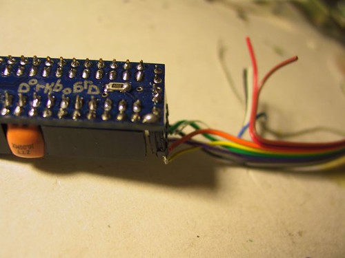
So you have a Dorkboard! Rad! First order of business, let's get it assembled so that we can have some fun with it.
Starting out
Your kit should have come with the following parts:
- Dorkboard prefab sweet blue PCB
- 10k ohm surface mount resistor (reset pullup)
- 180-470 ohm surface mount resistor (led current limiter)
- 0.1uF tantalum capacitor
- 4.7uF (or similar) electrolytic capacitor
- 16MHz ceramic resonator
- 28 pin IC socket
- 1 Atmel ATMEGA328P-PU IC (this is the microprocessor)
- 1 red LED (connects to pin 13)
- A long strip of male headers
- A long strip of female headers (not shown)

In addition to these parts, you'll need the following tools:
- Soldering iron
- Solder (you'll maybe get cancer slower with the unleaded kind)
- Dikes (fine tipped wire cutters/snips)
- (OPTIONAL) tweezers to help with the surface mounted parts
- (OPTIONAL) magnifying lens (to get a closer look at things
- (OPTIONAL) solder braid (for fixing mistakes)
- (OPTIONAL) helping hands or vice or clips or other holders
You should have a nice, well-lit, clean workspace. I think it's best to start with the difficult parts, so let's jump right on in to the surface mounted parts.
Mount the 10k SMT resistor
Locate the 10k surface mount resistor is labeled "103" (which means 10*10^3) or if there are 4 numbers it will say 1002 (100*10^2)). This will need to be soldered to the bottom of the board, closest to where the 5-pin header will go (just to the end of the word "dorkboard"). Even though the board is tinned, I like to put a bit of solder on each of the square SMT pads to make placement easier.
If your itsy bitsy SMT resistor is still in its packaging, you might need to use a hobby knife or razor blade to carefully remove it. It's small, so make sure it doesn't go flying away.
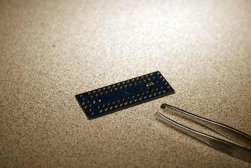
After putting a small bit of solder on the board pads, hold the resistor with tweezers with the numbers visible and carefully tack down one side. Once a good connection has been made, carefully tack down the other end of the resistor. Make sure that there is a good, continuous solder connection between the board, and make sure that the solder does not bridge to other intentional pads/places.
Mount the 220ohm SMT resistor
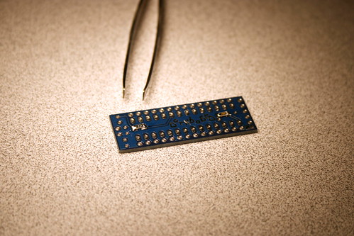
Just like the 10k resistor above, we will need to mount the 220 ohm surface mount resistor (labled 221 or 2200 the actual value of this part is somewhat arbitrary so it might also say 181,1800, 331,3300, 471,or 4700). The pads are also on the bottom side of the board, a bit to the left of the first "D" in "Dorkboard". Just like the part above, put a little extra tinning solder on the pads and then carefully tack down the resistor using tweezers and a steady hand.
Place the small orange capacitor
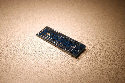
The small capacitor is the orange part with two pins (not the one with 3 pins -- that's the resonator....we'll get to her in a bit). From the top side of the board, poke its legs into position so that they poke through near the 220 ohm resistor placed in the last step. Solder down the legs on the bottom of the board and then trim them short using a pair of dikes. The image below shows the legs poking out:
LED party time
The tiny green LED is next. You'll orientation of this part is important....you want to make sure you don't have it spun around. If you do end up getting it backwards, it won't ruin the circuit -- but it won't ever light up for great blinkenlichtefreud. One of the LED pins is longer than the other -- that's the anode (positive terminal), and you'll want to make sure the long side is facing the outside edge of the board. Solder it down and then trim the legs short.
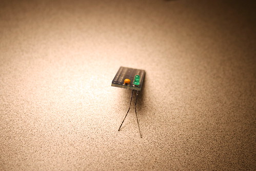
Electrolytic capacitor placement
The squatty fat little black and gray cylinder jobby is the electrolytic capacitor. It stores up some charge for when the rest of the circuit needs it. It's like a sexy little storage tank for (e-). The electrolytic cap must be seated in the proper orientation -- negative side (marked by the silver/gray band with (-) on it) facing toward the outside of the board.
Solder it down on the bottom of the board and then cut its legs short.
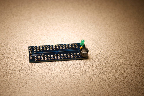
Ceramic resonator
The 3-pin ceramic resonator needs to be mounted on the top side of the board with 4 open pin holes on one side and 7 open pin holes on the other. She should be placed into the top of the board with 4 open pins between her and the squatty electrolytic punk from the previous step.
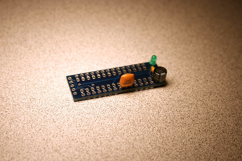
Although the orientation is not important, I like to put the printed text on the outside. Not only will this help me remember the speed at a later date, it's kinda like a status symbol: "Yo, 16MHz is how I be rollin!"
The pins aren't terribly long....you could probably live without trimming them, but if you like to keep it neat, cut her down to size.
IC socket action
Wow, we're done with all the discrete parts already? Time to move on to the IC socket. It's simple -- poke it into the top side of the board (it'll stay on its own once clicked in) and then solder it on the reverse. For consistency, make sure that the notch on the end of the socket is farthest away from the green LED (you'll thank me for this later). Solder cleanly, and don't bother trimming the pins.
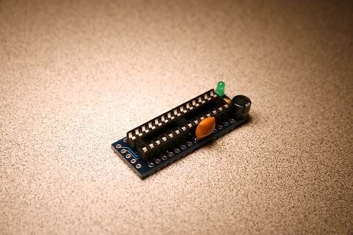
Programming header
There's a 5-pin programming header that should be mounted on the top side. If you got your kit from wulfden then it came with a single long strip of male header pins, simply use your dikes or some scissors to trim of a 5-pin section. Going in from the top of the board, poke the short pins down and leave the plastic pad and long side of the pins poking up at the top. Solder the short legs on the bottom side and don't bother trying to trim them.
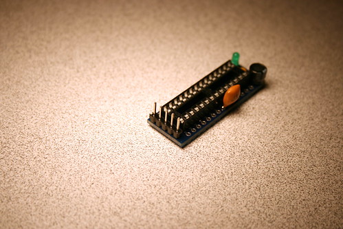 If you got your board from SuspectDevices or at one of the Dorkbotpdx workshops you will need to cut it from one of the female headers. Remove the 6th pin from the header as shown and then use your dykes to cut the header where the pin was.
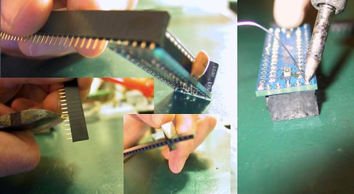
Dont forget the reset jumper
Assuming that you are using one of our programmers then put a blob of solder between the pads of the reset jumper as in the picture below.Pin headers and more pin headers
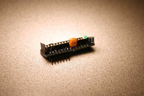
There are 3 sets of pin headers that must now be added to the board. All 3 will be mounted from the bottom...which means that the short side will poke out the top, the long pins will face down, and that they should be soldered on the top side of the Dorkboard (near the IC socket). As before, cut off the appropriate lengths as they are needed.
I chose to do the 7-pin header near the resonator first:
...and then the 4-pin:
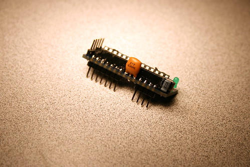
...and then the long 14-pin side:
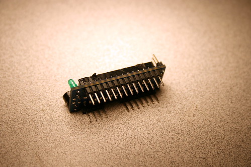
If you're extra super careful, you won't have to melt part of the IC socket like I did in the photo above. :)
Inserting the atmega328
Wow, we're almost done! All that remains is to insert the IC into the socket. Since it's probably the first time this chip has been mated with this socket, it may be a bit <ahem> tight. Simply use your thumb and forefinger to gently bend the IC pins inward about a half or 1 mm. Then insert the chip into the socket and make extra sure the notch on the chip aligns with the notch on the socket and is closest to the top-side 5-pin programming header.
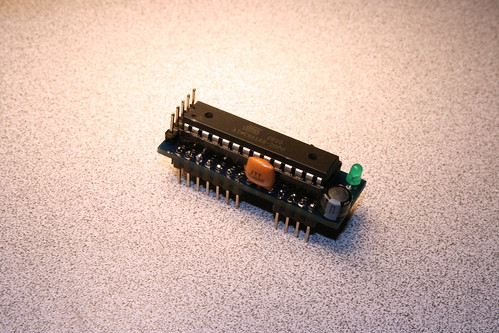
TIME TO PUNISH ELECTRONS!
Your Dorkboard is completed! Congratulations. It's now time to connect her up to your device programmer (maybe a Benito would come in handy here!), fire up the *rduino IDE, and let some code rip. Shred some code and make some art scream. Good day.
tbd: links to programming, troubleshooting, more info
