Preface:
This post will detail a couple of different ways that an external antenna can be added to the Raspberry Pi 3.
DO NOT TRY THIS AT HOME. ALL OF THE FOLLOWING WILL HAPPEN:
1) YOU WILL VOID YOUR WARRANTY
2) YOU WILL VIOLATE FCC REGULATIONS
3) THE PI'S WI-FI CERTIFICATION WILL BE VOID
IN ADDITION, YOU COULD EASILY DAMAGE YOUR PI
Please view this as a purely experimental exercise and proceed at your own risk.
It's not clear why an external antenna is not an option for the Pi 3, there are a number of possible reasons and I don't presume to know the Raspberry Pi Foundation's exact rationale. It could be to improve the out-of-box experience, an integrated antenna "just works" and there's no potential for the antenna connector to be broken plugging in an antenna. It could be to reduce complexity, the unit with an integrated antenna is compact and self-contained. It could be for regulatory reasons: in order to sell the device for use with a user-supplied antenna, the performance characteristics of that antenna need to be specified as part of the user instructions, and those characteristics must be adhered to in order to maintain compliance. Good luck with that.
Overview:
There are two basic approaches to adding a connector for an external antenna: remove the onboard antenna on the top side of the board and solder a coaxial pigtail in its place, or use the supplied pads on the bottom side and mount a U.FL connector. The first approach is much easier and can likely be accomplished with few special tools aside from a good soldering iron; however it results in compromised performance. The second approach involves precision soldering and is best attempted with strong magnification and a very fine soldering iron tip. Do not attempt it unless you're comfortable working with 0201 components (0.020" by 0.010", about the width of two and a half human hairs). It does result in substantially improved performance as compared to the top mount approach.
Top mount:
Start by removing the onboard antenna. Soldering tweezers or a heat gun can be used, or a well-tinned soldering iron with a sufficiently large tip. After removal, the board will look like this:
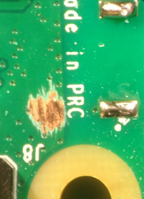
Note that some soldermask will need to be cleared away to attach the coax's shield, as seen to the left in the image. Next, prepare the coax tail. Strip the outer insulation back ~0.150" (3.75mm), tin the shield, then trim the shield back about 0.100" (2.5mm), finally, strip the center conductor about 0.050" (1.25mm) from the end. Solder the shield to the groundplane, and the center conductor to the antenna feed pad. The finished result will look like this:
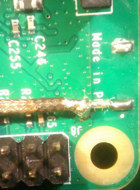
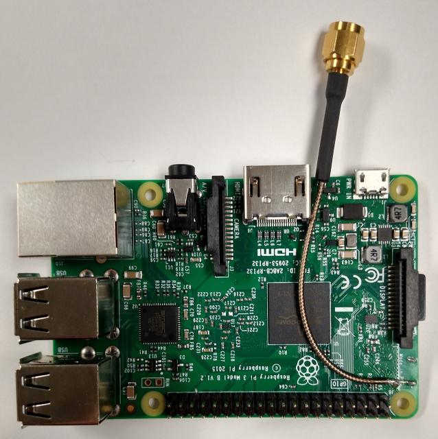
The finished product, with coaxial "tail" attached will look like ths:
U.FL Connector:
Mounting a U.FL connector to the board is straightforward for those with experience working with miniscule surface mount devices. It involves clearing some soldermask and rotating one zero-ohm resistor.
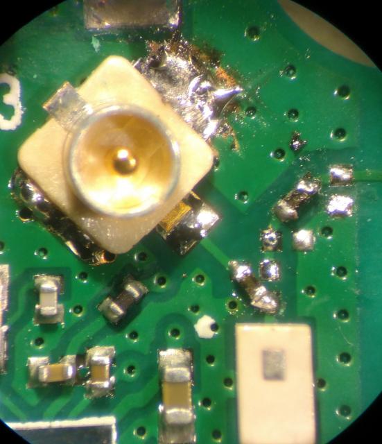
Here is a U.FL connector overlaid on the provided pads:
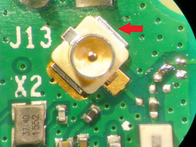
Note that while the U.FL connector fits very well on the two exposed pads, there's soldermask covering the area where one of the leads falls. While you could just solder the two exposed pins, for mechanical robustness and optimal RF performance it's best to clear out that solder mask and solder the lead. After mounting the U.FL, rotate the resistor nearest the output filter, the large white device in the bottom of the image, 45 degrees to the left. The result will look like this:
Be careful not to short ground to the header pin just above the connector.
Another approach would be to cut the output trace leading to the antenna and add a solder blob to bridge the output trace to the trace leading to the U.FL connector. I haven't tried this, but I don't see any reason it wouldn't work, though likely with some adverse impact on the RF performance.
Performance:
I configured my Raspberry Pi 3 as an access point following the excellent instructions here:
https://learn.adafruit.com/downloads/pdf/setting-up-a-raspberry-pi-as-a-wifi-access-point.pdf
After completing the steps in that procedure and rebooting, I was able to connect to the Pi with my Android phone. Using a spectrum analyzer with an attached rubber duckie antenna, I was able to observe the AP beacon packets being transmitted. I captured the transmitted beacon spectrum at channels 1, 6, and 11 (2412, 2437, and 2462 MHz), then moved on to conducted measurements.
I observed the conducted output power of the Pi using a Tektronix MDO4000-series mixed-domain oscilloscope, using an RF power trigger on the beacon packets. Power measurements were calibrated to an HP 8481D power sensor. The observed RF output powers are shown below:
| Channel | Frequency | Coaxial tail output power | U.FL output power |
|---|---|---|---|
| 1 | 2412 MHz | 14.13 dBm | 15.98 dBm |
| 6 | 2437 MHz | 13.67 dBm | 16.15 dBm |
| 11 | 2462 MHz | 13.47 dBm | 16.39 dBm |
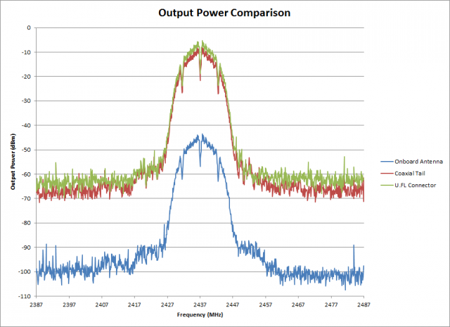
The U.FL numbers are consistently 2-3 dBm higher, almost a doubling in conducted power at the high end of the band. This is due to the massive impedance discontinuities presented by the antenna feed trace and the exposed center conductor of the coaxial cable. While it's likely possible to recoup some of that with RF tuning using the series and shunt placements in the RF path, at that point it makes more sense to go to the U.FL connector approach. A comparison of the output spectra is shown below, with no compensation applied (hence the radiated power is much lower than the conducted powers). All graphs use a resolution bandwidth of 10 kHz.
A normalized graph showing the relative spectral regrowth is below.
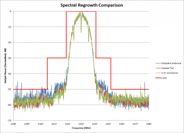
This graph is useful for comparing the in-band noise performance of the various approaches. The onboard antenna fares the worst close-in to the carrier, likely due to either fundamental mismatch or poor harmonic termination impacting power amplifier linearity. Further out the spectra become more comparable. The violating spikes are transient in nature, not part of the modulated waveform. Also, the resolution bandwidth used here is incorrect, it should be 100 kHz for 802.11 spectral mask measurement.
Future Work:
No attempt has been made to characterize out-of-band performance, or performance with any particular make or model of external antenna. A more comprehensive review of spurious and harmonic emissions is advised. Also, while it's likely that the U.FL and coaxial cable approaches lead to satisfactory WLAN performance, further analysis of adjacent channel power and error vector magnitude would be wise.