So have you ever wanted to use one of the ubiquitous 16 pin LCDs in a project but found it a pain to wire up all the signals (not to mention the pot for contrast control and maybe a backlight control as well)? Me too. Sure there are serial backpacks and other ways to cut down on the number of pins and connections that it takes to run the LCD but sometimes that seems like overkill for a simple one-off project.
When I took Don's Eagle class I needed a good small project to start off with. We were allowed 2 square inches on the DorkbotPDX PCB group order and it seemed like this would be a perfect opportunity to come up with a good solution to the LCD problem. So I decided to generate a design which is basically a Dorkboard on an expanded layout with the necessary header, connections and discrete components to drive the usual 16 pin LCD displays based on the Hitachi HD44780 and compatible controllers (including backlight PWM control). The Eagle files are attached as is a schematic image. It incorporates a new layout of Don's Dorkboard circuit. I left out a couple of features of his design: the pin 13 LED (which I didn't really want blinking away behind the LCD) and the optional DTR autoreset capacitor, which I didn't need since the USB-serial programmers I use (like the Benito) handle the reset pulse in other ways.
The idea was that you would then have a board which could be used as a Dorkboard (Arduino compatible except for the missing LED) but with the ability to easily plug in an LCD for a nice compact package. You can drive it with the LiquidCrystal library which comes standard with the Arduino software. In addition, since serial and I2C lines are brought out on the board, you could use the board + LCD as a serial display to another processor if you needed more processor power or additional I/O pins.
The resulting board: 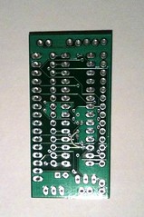
First one built out: 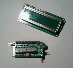
And running it's first program: 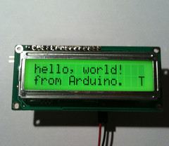
There were a couple of errors in the board (which are fixed on the attached Eagle files). One was an incorrectly wired pin on the MCU which I missed on proofreading the schematic (you have to be careful when you name nets in Eagle and allow it to autoconnect the signals). Fortunately, it was easy to cut a trace and attach a jumper wire at a convenient via to correct this. The other error is that there are a few surface mount components which I meant to have on the bottom side of the board. Somehow I failed to put them there but they are under the socket and are small enough so that they still fit fine. But it isn't the best arrangement since once you solder on the socket, you can't get to those components to fix any soldering problems. So you do it right the first time.
All of the example programs for the LiquidCrystal library seem to work fine. Here is one of my first test programs:
include <LiquidCrystal.h>
// LiquidCrystal display with: // rs on pin 12 // rw is pin 11 // enable on pin 6 // backlight control on pin 5 (pwm 0=bright, 511=off) // d4, d5, d6, d7 on pins 7, 8, 9, 10
define D4 7define D5 8define D6 9define D7 10define RW 11define E 6define RS 12define BL 5
LiquidCrystal lcd(RS, RW, E, D4, D5, D6, D7); int blevel = 0; int blev_steps = 50;
void setup() {
delay(2000); lcd.begin(2,16); // Print a message to the LCD. pinMode(BL, OUTPUT); analogWrite(BL,blevel); lcd.print("Hello, world!"); lcd.setCursor(0,1); lcd.print("1234567890123456789012345678901234567890");}
void loop() {
// scroll 13 positions (string length) to the left // to move it offscreen left: for (int positionCounter = 0; positionCounter < 13; positionCounter++) { // scroll one position left: lcd.scrollDisplayLeft(); // wait a bit: delay(150); } // scroll 29 positions (string length + display length) to the right // to move it offscreen right: for (int positionCounter = 0; positionCounter < 29; positionCounter++) { // scroll one position right: lcd.scrollDisplayRight(); // wait a bit: delay(150); } // scroll 16 positions (display length + string length) to the left // to move it back to center: for (int positionCounter = 0; positionCounter < 16; positionCounter++) { // scroll one position left: lcd.scrollDisplayLeft(); // wait a bit: delay(150); } // delay at the end of the full loop: delay(1000); for (int j=blevel;j<blevel+blev_steps;j++) { analogWrite(BL, j); delay(20); } blevel += blev_steps; if (blevel > 511) blevel = 0;}
I measured about 17uA draw with the backlight off and about 65uA with it full on with the particular 2x16 LCD I had in case anyone was interested in a compact LCD equipped, battery powered Arduino compatible.
I had the parts to build two of these boards and I promised Don the third one so that is it for this order. There are a few things I think I would change on a second version. The output headers were done in a hurry without a lot of thought. The serial output pins are redundant with some of the programming header pins and I'd like to find room for a standard 6 pin ISP header so that it would be easy to use the board outside of the Arduino environment. And I think adding the optional DTR reset capacitor would be a good idea. I will probably generate a new layout with those features and put some into the next group PCB order.
I'm primarily a scientist and software guy by training and experience although I've dabbled in lab automation and electronics off and on. I'm sure some of my fellow Dorkbots could generate a more professional design but I managed to get a functional and useful board out of my first try so I'm pretty satisfied.