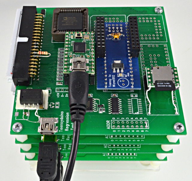
Over the last couple weeks I've been working on a automated test system for Teensyduino, which someday will verify nearly all the Arduino functionality on every board and also test most of the Arduino libraries. Here's what my first try looks like.
Click "Read more" for another photo, a bit of discussion about how this works (and what doesn't work so well), and a peek at what will be my second attempt.
The main idea, which began in November 2012, behind this test is the use of AD75019 switch matrix chips to allow the control board (on top) to configure which pins on the other 3 boards (the test boards, each with a different Teensy) connect to each other and to various peripheral hardware.
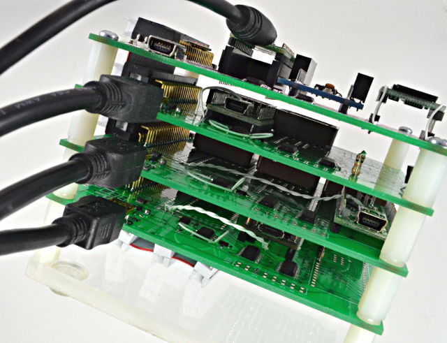
Here's a peek inside....
The switch matrix chips provide a 16 signal bus. Any pins from any of the test devices and some peripherals on the top board can be connected to any of the 16 signals.
At first, I started building on the (now abondoned) ArduinoTestSuite project started by Mark Sproul, Matthew Nurdoch, and Rick Anderson. A good number of the tests were ones I wrote and contributed while debugging the Arduino String functions, plus a couple others. Sadly, that code is filled with AVR-centric design that doesn't play nicely with Teensy 3.0. There's a tremendous amount of complex code just for printing stuff, and it's in a style I don't like with complex naming conventions for even the simplest things! I ended up pulling out the String and pulseIn test I wrote, and modeled some of my new tests after theirs, but none of the original code has remained. It was just easier to rewrite everything in a much simpler way. But their work was tremendously helpful as a starting point and inspiration for this project. Rick, Mark, Matt... if you're reading this, thanks. :-)
One of my goals with this design was to create a multi-board test. In ArduinoTestSuite, the paradigm is the code runs on a single board and prints messages about success or failure. For testing something like Tone, this model works pretty well. The tone is created in the background by interrupts, while the main program rapidly polls the signal with digitalRead(). The hardware requirement is simple, just 2 pins connected together (or with the switch matrix, those 2 pins both connected to 1 of the 16 bus signals).
However, the single board approach is pretty limited. For example, testing delay() with this code is pretty pointless. Since delay() and millis() are implemented by the same software, very few types of defects would be detected by this single board test. I wrote a 2-board delay test, where the first board uses digitalWrite() with a delay(), and the second board measures the actual delay with digitalRead() and micros(). A future version might use timer hardware for higher accuracy, but even software polling works very well. The test runs twice, once with an AVR-based Teensy 2.0 sending and a ARM-based Teensy 3.0 receiving, and then vise versa. They're different processors and different code bases.... so if a regression happens someday causing delay() to break or become inaccurate, hopefully only 1 will break, or they might break differently, but much better odds of automatically detecting the defect.
Currently, the control board implements 5 simple text-based commands, a few to configure the switch matrix, one to configure which Teensy is "active" (more on that in a moment), and a command to reboot the active Teensy, which causes it to be reprogrammed.
So far, the software side on my PC is very simple. I back-ported Arduino 1.5.2's command line inputs to 1.0.4 (any copy of Arduino modified by Teensyduino has this). A makefile just runs Arduino to compile the code. Teensy Loader supports a programming mode where you use Verify in Arduino, which causes the Teensy Loader to update with the freshly compiled code, and the you press the button to reprogram. After Arduino compiles the code, the makefile runs a program to send the commands to the control board, which configure the switch matrix and reboots the Teensy to run the test. Then after a 1 second delay, another program waits for that Teensy to come online, captures its Serial.print() output and parses for a message indicating success or failure.
Each single board test is 3 components: the .ino program which does the test and prints success or fail (and optionally info as it does the test), the script to send to the control board causing the switch matrix to be configured, the desired test Teensy selected and rebooted, and the makefile to compile, send the script and run the result capture. Each test has its own tiny makefile. A master makefile just runs them all. If any step anywhere fails, make stops the "build". It's all just relatively simple makefiles to compile the code, configure the hardware to start the test, and capture the result. Some day this might integrate with a fancy system like Jenkins, but for now I'm focused on just keeping it all very minimal makefile which I continue to develop.
The active board command selects which of the board will receive all the other commands. It's a very simple system. One key component is a USB disconnect switch. The control board is always connected. Only one of the other boards can connect to USB. I put FSUSB30 switches on each board. If you look at the photo above, you'll see a pair of wires soldered from each Teensy's USB to the test board, so the USB goes through those FSUSB30's to allow the control board to connect only the active Teensy.
The 2-board test was a challenge. It turned out to be somewhat difficult to get the transmitting board, which is programmed and boots up first, to reliably wait until the receiving board is read for the test signals to begin. After much frustration with simple high-low or low-high transitions, I ended up building something that's probably overkill, but works very reliably. A sequence of high-low, low-high transitions is sent with distinctive timing.
void RegressionTestClass::sendSignal(uint8_t pin)
{
digitalWrite(pin, HIGH);
pinMode(pin, OUTPUT);
digitalWrite(pin, HIGH);
delayMicroseconds(6000);
digitalWrite(pin, LOW);
delayMicroseconds(1700); // 3 distinctive pulse widths, very unlikely
digitalWrite(pin, HIGH); // to occur randomly while boards reboot
delayMicroseconds(3900); // or the switch matrix is reconfigured
digitalWrite(pin, LOW);
delayMicroseconds(4700);
digitalWrite(pin, HIGH);
}
The receiver waits for this sequence, with some tolerance in the timing, but it must match very closely:
void RegressionTestClass::waitForSignal(uint8_t pin)
{
elapsedMicros usec;
unsigned long t1, t2, t3;
pinMode(pin, INPUT_PULLUP);
while (1) {
//Serial.println("begin waitForSignal");
while (digitalRead(pin) == LOW) ; // wait
while (digitalRead(pin) == HIGH) ; // wait
usec = 0;
while (digitalRead(pin) == LOW && usec < 1850) ; // wait
t1 = usec;
//Serial.print("t1=");
//Serial.println(t1);
if (t1 < 1600 || t1 >= 1850) continue;
while (digitalRead(pin) == HIGH && usec < 5900) ; // wait
t2 = usec;
//Serial.print("t2=");
//Serial.println(t2);
if (t2 < 5500 || t2 >= 5900) continue;
while (digitalRead(pin) == LOW && usec < 11000) ; // wait
t3 = usec;
//Serial.print("t3=");
//Serial.println(t3);
if (t3 < 10200 || t3 >= 11000) continue;
return;
}
}
With this signalling in place, building the 2-board test became fairly easy. It has 5 components: the 2 .ino files for the sender and receiver, the 2 control board scripts to cause each to be programmed and of course configure the switch matrix to route the signals between the boards, and the makefile to run the commands.
However, as I've worked with this, one pretty serious limitation has come up. The AD75019 switches are about 200 ohms on resistance. I'm powering it with 12 volts. 24 volts apparently gives about 150 ohms, but that's only a small improvement.
The problem is this design has a lot of capacitance on those 16 shared bus signals. The run through that ribbon cable to every board, and on each board to 2 or 3 of the switch matrix chips. The wires on each board between the Teensy and the switch matrix aren't short either, since the board has places for 3 different Teensy boards, so they add some capacitance. To route any signal between 2 points, it has to go through a 200 ohm switch to one of the bus signals, then through another 200 ohm switch driving a lengthy wire at the destination.
The result is about 2 MHz bandwidth. That works great for many types of tests, but for SPI-based tests like the Ethernet and SD library, it's a real problem.
It turns out the Teensy 3.0 test on Ethernet can just barely work, because it's sending 3 volt signals and the W5100 chip is looking for 3 volts. The SCK clock looks pretty terrible... pretty much a triangle wave with curved slopes, but it just barely works. But a 5 volt signal bandwidth limited ends up spending too much time high when received by the 3 volt (but 5V tolerant) ethernet module. I got an Ethernet test to work by configuring the Teensy 2.0 to run at 8 MHz. So far, I haven't been able to make the SD library test work at all.
Over the last few days I've been considering many other options. I designed a bigger version of this board with a couple old SpartanXL FPGAs I have left over from the ancient MP3 player project (from long before Apple sold their first iPad). Those old FPGAs are 5 volt tolerant, which is important. The board grew in size and had to grow to 4 layers to route, and since this basically adds yet more stuff, it probably increases the capacitance problem even more. I did a preliminary design for a big digital mux similar to the switch matrix, but not bidirectional like the analog switches, really unidirectional 2 ones in the same chip.
I was about to send this board to fab, but then had a lot of second throughts. One big one was the Xilinx software said the pad-to-pad timing was 20 ns. That's not bad, but this design required the signal to go through 2 of those paths, so 40 ns from the Teensy to the SD card. Then the MISO signal goes through 40 ns to get back. I orginally has reservations about the analog switches being too slow, but I just wanted to get the project started. Now I had this feeling again.....
So of course I redesigned everything!
I had a epiphany that a single test system didn't need to cover every possible scenario. Simple, right? Well, I had designed a mostrously complex 4 layer board to add those FPGAs, and even that might not be good enough. So instead, I started work on a fast digital-only board. Rather than make a shared bus that's extremely flexible and expandable, I just went with connecting every pin from the 3 test boards to a FPGA I/O pin. Reconfiguring the FPGA can serve to route the signals. I'm not going to implement a big switch matrix (I did draw up a design... it's a huge monster), but rather keep things extremely simple and do a new FPGA configurations for each test, which will probably be a trivial schematic with just a few buffers connecting one FPGA pin to another. That can get the delay into the 10ns range.
I also discovered Xilinx made one more generation, the Spartan2, which is 5 volt tolerant. Luckily, they're still readily available. Xilinx has long since dropped support for those chips from their software. The don't publish old versions. But as luck would have it, I still have the original Foundation 3.1 software and even a service pack they published plus a disc with the documentation of that era (none of these things are still available from Xilinx).
So, here's my next attempt, which was sent to fab yesterday.

It's got the 3 Teensy boards with every digital pin connected to a FPGA pin. 12 signals go to 2 different ethernet modules and a SD card, and 17 signals go to header that I'll use to connect other peripherals as I expand my testing to cover more Arduino libraries.
The key point though, is this high speed digital board is only needed for the tests that can't run on the stack of boards with the more flexible analog switch matrix. The analog switches are really very nice, despite the limited bandwidth, because they're bidirectional and, well, analog.
Over time, I intend to develop automated tests for all the standard Arduino functionality and probably most of the Arduino libraries officially supported on Teensy. That list of libraries will probably double over the next year too, since I have a big box of purchased hardware sitting right here. I plan to start incorporating them into this automated testing as much as I reasonably can.
Hopefully over the long term, this effort will really improve the code quality of Teensy's support for Arduino usage. It might also really benefit regular Arduino users too. Already with only just 6 tests implemented, I've discovered a couple bugs, one of which appears to also be in Arduino 1.5.2 for Arduino Due. I'm planning to contribute a fix to them soon.
I'll probably post more here as this system develops. If anyone is interested (or if anyone actually read all this), please let me know in the comments below? Also, before anyone asks about fancy Continuous Integration systems, see my note above about keep this as simple as possible while developing the basic system.