Thanks to the amazing effort of Frank Boesing, the Teensy Audio Library now has native S/PDIF output.
Using a $1 TOSLINK connector, or just a red LED, you can get optical S/PDIF digital audio output.
Optical output is useful for projects where Teensy connects to grounded equipment. There are lots of ways to simply play sounds, but the Teensy Audio Library gives you Arduino-sketch controlled synthesis, mixing, effects & filters, analysis and much more. Sketch controlled sound is most useful when you connect more hardware to Teensy & use other Arduino libraries for inputs. But often that other hardware comes with ground connections that cause audio-corrupting ground loop problems with analog audio, like the DAC pin or the audio shield. Optical S/PDIF give you perfect digital audio output for those projects!
Click "Read more" for much more detail about the S/PDIF development....
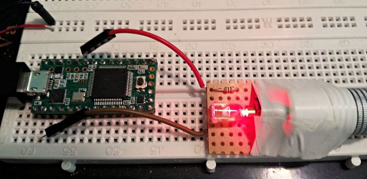
When Frank started the thread about S/PDIF encoding, I must confess my only knowledge of S/PDIF encoding involved using an expensive chip to convert digital I2S format audio. But it turned out that all the S/PDIF encoding can be done in software, with the encoded signal output on a single pin. You can even use a red LED to transmit the signal into a TOSLINK optical cable!
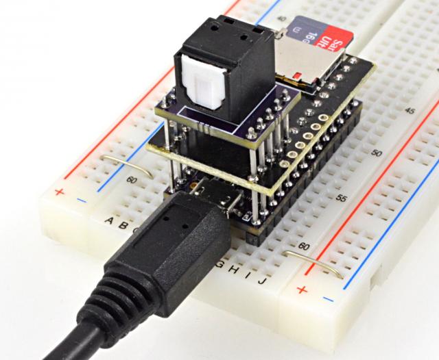
Of course, the proper way involves a TOSLINK connector. Fortunately, they're cheap. I found Everlight PLT133/T6A at Digikey, part number 1080-1434-ND (currently only $1.00), and I created this little circuit board at OSH Park (a set of three is $1.90)
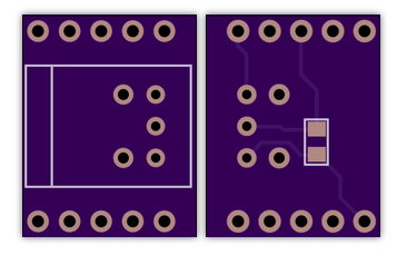
As you can see, the PCB is extremely simple. The connector just needs 3.3V power and the signal from pin 22. There's one 0.1 uF decoupling capacitor, but that's it. The connector just has a LED and buffer circuit inside.
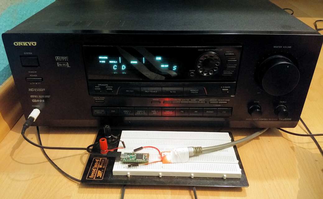
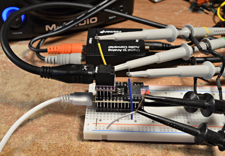
Here it is running, through a S/PDIF to analog converter and monitor speakers.
All the S/PDIF encoding is done in software, to make the fully encoded signal appear on pin 22.
S/PDIF uses a 32 bit format for each sample, where 20 bits represent the audio data. The data is send LSB first. The other 12 bits include a preamble, so the decoder can recognize where each 32 bit, and some other data fields we can (mostly) ignore.
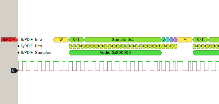
Except for the preamble, the each bit is biphase mark encoded, which just means it's transmitted as 2 bits. A zero is transmitted as 2 identical bits, with a change before the next transmitted bit. A one is transmitted as 2 different bits. The result is a AC only waveform, because every bit causes either 1 or 2 transitions.
Frank used some crafty optimizations to achieve the S/PDIF encoding. He used a lookup table to convert each 8 bits of audio data to the biphase mark format. The lookup table also reverses the bit order.
static const
uint16_t bmclookup[256] = { //biphase mark encoded values (least significant bit first)
        0xcccc, 0x4ccc, 0x2ccc, 0xaccc, 0x34cc, 0xb4cc, 0xd4cc, 0x54cc,
        0x32cc, 0xb2cc, 0xd2cc, 0x52cc, 0xcacc, 0x4acc, 0x2acc, 0xaacc,
        0x334c, 0xb34c, 0xd34c, 0x534c, 0xcb4c, 0x4b4c, 0x2b4c, 0xab4c,
        0xcd4c, 0x4d4c, 0x2d4c, 0xad4c, 0x354c, 0xb54c, 0xd54c, 0x554c,
        0x332c, 0xb32c, 0xd32c, 0x532c, 0xcb2c, 0x4b2c, 0x2b2c, 0xab2c,
        0xcd2c, 0x4d2c, 0x2d2c, 0xad2c, 0x352c, 0xb52c, 0xd52c, 0x552c,
        0xccac, 0x4cac, 0x2cac, 0xacac, 0x34ac, 0xb4ac, 0xd4ac, 0x54ac,
        0x32ac, 0xb2ac, 0xd2ac, 0x52ac, 0xcaac, 0x4aac, 0x2aac, 0xaaac,
        0x3334, 0xb334, 0xd334, 0x5334, 0xcb34, 0x4b34, 0x2b34, 0xab34,
        0xcd34, 0x4d34, 0x2d34, 0xad34, 0x3534, 0xb534, 0xd534, 0x5534,
        0xccb4, 0x4cb4, 0x2cb4, 0xacb4, 0x34b4, 0xb4b4, 0xd4b4, 0x54b4,
        0x32b4, 0xb2b4, 0xd2b4, 0x52b4, 0xcab4, 0x4ab4, 0x2ab4, 0xaab4,
        0xccd4, 0x4cd4, 0x2cd4, 0xacd4, 0x34d4, 0xb4d4, 0xd4d4, 0x54d4,
        0x32d4, 0xb2d4, 0xd2d4, 0x52d4, 0xcad4, 0x4ad4, 0x2ad4, 0xaad4,
        0x3354, 0xb354, 0xd354, 0x5354, 0xcb54, 0x4b54, 0x2b54, 0xab54,
        0xcd54, 0x4d54, 0x2d54, 0xad54, 0x3554, 0xb554, 0xd554, 0x5554,
        0x3332, 0xb332, 0xd332, 0x5332, 0xcb32, 0x4b32, 0x2b32, 0xab32,
        0xcd32, 0x4d32, 0x2d32, 0xad32, 0x3532, 0xb532, 0xd532, 0x5532,
        0xccb2, 0x4cb2, 0x2cb2, 0xacb2, 0x34b2, 0xb4b2, 0xd4b2, 0x54b2,
        0x32b2, 0xb2b2, 0xd2b2, 0x52b2, 0xcab2, 0x4ab2, 0x2ab2, 0xaab2,
        0xccd2, 0x4cd2, 0x2cd2, 0xacd2, 0x34d2, 0xb4d2, 0xd4d2, 0x54d2,
        0x32d2, 0xb2d2, 0xd2d2, 0x52d2, 0xcad2, 0x4ad2, 0x2ad2, 0xaad2,
        0x3352, 0xb352, 0xd352, 0x5352, 0xcb52, 0x4b52, 0x2b52, 0xab52,
        0xcd52, 0x4d52, 0x2d52, 0xad52, 0x3552, 0xb552, 0xd552, 0x5552,
        0xccca, 0x4cca, 0x2cca, 0xacca, 0x34ca, 0xb4ca, 0xd4ca, 0x54ca,
        0x32ca, 0xb2ca, 0xd2ca, 0x52ca, 0xcaca, 0x4aca, 0x2aca, 0xaaca,
        0x334a, 0xb34a, 0xd34a, 0x534a, 0xcb4a, 0x4b4a, 0x2b4a, 0xab4a,
        0xcd4a, 0x4d4a, 0x2d4a, 0xad4a, 0x354a, 0xb54a, 0xd54a, 0x554a,
        0x332a, 0xb32a, 0xd32a, 0x532a, 0xcb2a, 0x4b2a, 0x2b2a, 0xab2a,
        0xcd2a, 0x4d2a, 0x2d2a, 0xad2a, 0x352a, 0xb52a, 0xd52a, 0x552a,
        0xccaa, 0x4caa, 0x2caa, 0xacaa, 0x34aa, 0xb4aa, 0xd4aa, 0x54aa,
        0x32aa, 0xb2aa, 0xd2aa, 0x52aa, 0xcaaa, 0x4aaa, 0x2aaa, 0xaaaa
};
Each 16 bit audio sample only needs 2 lookups in this table to convert to biphase mark encoded format, with the bits properly reversed.
Rather than compose each 32 bit frame, Frank's code uses another trick to treat the 16 bit audio as one part (resulting in a 32 bit data word written to the DMA buffer that will ultimately get transmitted on pin 22) and the remainder of the the S/PDIF frame and a portion of the next frame as the other 16 bit part. That second part is mostly static data, which changes every 192 frames when S/PDIF needs a different preamble.
The encoded data is piled up into a DMA buffer, where the I2S peripheral simply streams it to pin 22. The I2S has to be run faster than normal, since it's transmitting many more bits per sample. The normal I2S clock signals output are disabled, unless you uncomment them in the code (as was done in the test above, where you can see oscilloscope probes measuring them).
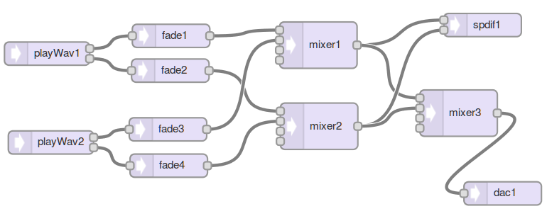
Of course, you don't need to worry about all this low-level encoding stuff to actually use the S/PDIF output. The S/PDIF output object is available in the Audio System Design Tool, so you can easily connect it to other stuff from the audio library.
For example, here's a design that allows simultaneously playing 2 .WAV files from a SD card, with sketch-controlled cross fading between them. The stereo output goes to the S/PDIF output, and also gets mixed to mono and sent to the 12 bit DAC pin.
While the S/PDIF support is completed and available on Github, I do have another improved S/PDIF circuit board planned.
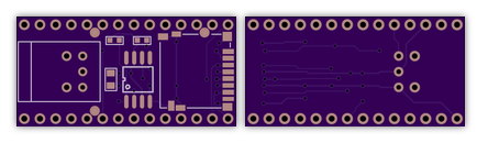
This one is untested, but you can get it at OSH Park if you want it now! It's the same TOSLINK connector as above, but with the SD card socket and a SPI Flash chip compatible with the SerialFlash library. Future versions of the audio library will support these chips, which have much lower latency than SD cards, to allow many more simultaneous "voices" for polyphonic sample playback. Future wavetable synthesis features are also likely to uses these low-latency flash memory chips.
With either board, or even just with a red LED, you can get optical S/PDIF digital audio output from the Teensy Audio Library, for great quality sound.