I recently acquired a
tri-color LED Matrix display from
SparkFun.
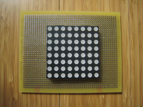
I bought it "bare" (with no controller), for the challenge of setting it up, and I'm finally getting around to doing it.
The first challenge was figuring out the pinout. The
datasheet was, er.. "unclear".
Here's what I've figured out:
(R,G,B)
Cathodes --
Column 1 - (32, 2, 1)
Column 2 - (3, 30, 31)
Column 3 - (29, 5, 4)
Column 4 - (6, 27, 28)
Column 5 - (12, 22, 11)
Column 6 - (20, 13, 21)
Column 7 - (15, 19, 14)
Column 8 - (17, 16, 18)
Anodes --
Row 1 - 26
Row 2 - 25
Row 3 - 24
Row 4 - 23
Row 5 - 10
Row 6 - 9
Row 7 - 8
Row 8 - 7
So, to turn on the red LED on Row 4, Column 5, you'd need to give power to pin 22 and sink pin 23.
I think the best way to do this is with four 74HC595 shift registers, thirty-two 2n3904 transistors, and 8 current limiting resistors.
I just hope I can shift out 24 bytes of information quickly enough that there's no flicker.
Update, 4/08/08 --
So, my first attempt was a bit of a failure. for two reasons:
* I thought the rows were cathodes and the columns were anodes. Turns out I had it backwards, and had already soldered in all my transistors onto the board.
* I have never soldered on perfboard before, and thought I'd be able to bridge the pads easily with solder. Not so. Not so at all.
So, I could continue on this board, soldering down 100 little wires that don't want to be soldered down, or start afresh with a new board. I'm going to do the latter.
Or maybe I'll do my very first PCB?