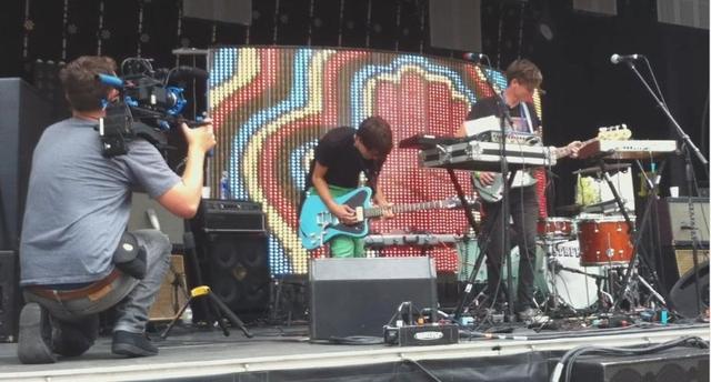
Several months ago, I was approached by the Portland band Starfucker (STRFKR) to build them an LED video wall for their upcoming tour. It needed to be large, bright, and durable, but also lightweight, portable, and easy to set up and tear down. They wanted to be able to plug in an iPod or iPad and play videos that are synced up along with their click track so everything goes along perfectly with the music. I enlisted the help of Alex Norman to take care of the software side of the project, and got to work trying to figure this thing out. It seemed like it could be made with mostly off-the-shelf components, and indeed that turned out to be the case. We decided that we would open-source the entire project, for the good of all mankind.
CLICK HERE FOR A VIDEO FROM ITS FIRST PERFORMANCE.
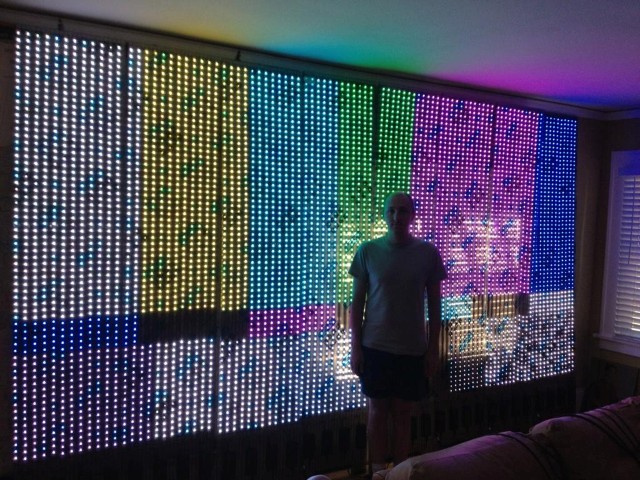
It didn't take long to find Adafruit's Digital Addressable RGB LED w/ PWM waterproof flexi strip, which looked like a good, simple solution for the pixels and drivers, since they all come together on a flex circuit and all you have to do is provide power and "SPI-like" data and clock signals. The LEDs are very bright, and they come in 5-meter-long strips with 32 pixels per meter. We used a total of 192 meters of strips to create a 64x96 pixel display with a 2:1 aspect ratio. The screen size is 6-1/2' tall by 13' wide, the entire wall is 8'x13'.

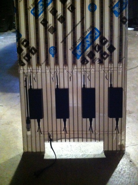
Adafruit provides a suitable power supply for these, the 5V 10A switching power supply, which is good for 5m of LED strip at full-duty. I stretched it to 6m per PSU, because that made the physical layout work perfectly and I didn't expect they'd need to light up the wall full-white. We used 32 of these supplies to power the strips, each supply took care of three columns of pixels.
For the main structure of the wall, I found a polycarbonate panel made for use in greenhouses. It's very light-weight, structurally stiff, and nearly indestructible. Multi-Craft Plastics in Tigard has it in-stock locally, in up to 6'x24' size(!), in clear, bronze, and translucent milk colors. I chose the 16mm bronze triple-wall panel because its thickness makes it stiff enough for handling, and the bronze tint makes it fade into the background a little better without affecting the LED color much at all.
We used four 4'x8' panels, ordered ripped in half from Multi-craft so they would fit in my car, and then trimmed them down to 20" (24 cells) wide with a flush-trim router bit. I also bought sixteen 12' strips of polycarbonate U-profile to finish the edges after it was all done.
The real beauty of the 16mm triple-wall panels is that the cross-sectional cell size is perfect for the LED strips to fit inside.
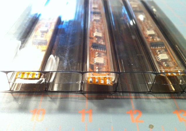
In fact, all off the electronics except for the power supplies were designed to fit completely inside the panel. This made it a bit of a ship-in-a-bottle type of construction project, but the band wanted something that an excited fan could throw a beer all over without harming it or shorting anything out.
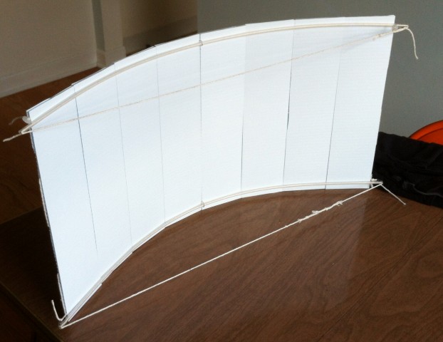
Before installing the electronics, however, I had to figure out how the wall could unfold to support itself without needing the usual truckload of space trusses. I suspected that by connecting the panels tightly with cord and curving the wall, it would be able to support itself stably without needing anything in the way of external supports. An 1/8-scale model proved the concept:
And here it is full-size:
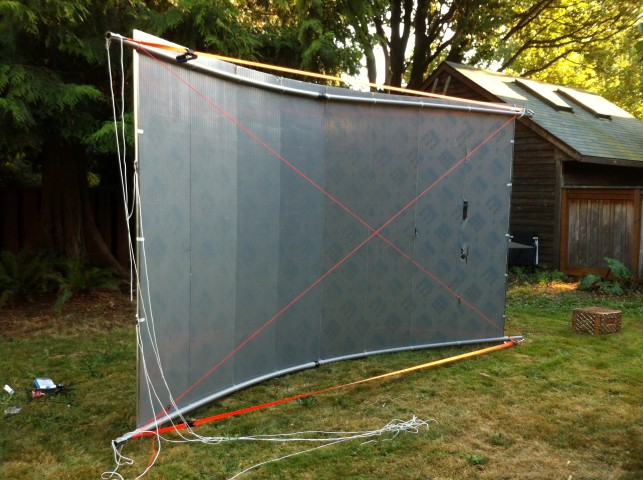
1-1/4" conduit tensioned by cam straps provide the curvature. I used 1/8" dacron cord (500-lb breaking strength) to connect the panels together, lash them to the conduit, and cross-tension the corners for rigidity. There's a clever little cord tensioner/carabiner combo called a Figure-9, which does very nicely to tighten everything up. It's basically a mechanical version of a trucker's hitch, but easier to tie.
So, confident about the structural integrity, it was time to prepare the panels to receive the electronics. I made a couple of router/drill templates to cut out holes in the front face for wiring and for the power supplies to sit in.
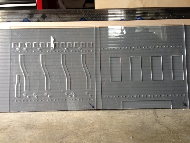
Then I drilled long 1/4" holes from the sides to accept bus wires for the power. It may seem like I could have made life easier by just routing out large swaths of panel and stuffing everything from the front, but that would have destroyed the structural integrity of the panels so I tried to keep as much of the front face intact as possible and only cut into single cells wherever I could.
Each panel gets a female XLR (microphone) jack to receive data. XLR is nice because it has three conductors so we could have Clock, Data, and Ground to each panel. It's also nice because the cables are easy to find on the road, in case one develops a bad connection. But they're also very robust connectors. The clock and data lines enter the first LED strip, and then zig-zag across the panel from left to right.
Here's a detail showing the internal wiring. You can see the bus wires going across. I used 16 gage bare copper wire for the 5V DC and ground lines above the power supplies, and 12 gage for AC across the bottom. Each panel has a male and female (not shown) electrical jack so the AC supply can be daisy-chained between panels. Besides the fact that all the soldering had to be done "thru-hole," the electronics on this is really simple. Disclaimer: I'm not sure the Underwriter's Laboratories would love everything I did here, but I tried my best to make sure it's safe. BTW this thing sucks about 15A of juice, at full load.
(If I had this to do again, I think I'd design circuit boards to accept all of the wiring, instead of doing this bus wire concept. It would have made life a lot easier.)
After soldering and testing each panel, I taped over the holes with two layers of gaffer's tape. Then I cut U-channel to go all around the outside edge. I also gaffed the U-channel on, so the whole wall can be very easily disassembled for repair. Basically, the whole thing is held together with tape, string, and cable ties.
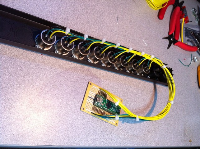
The control box is the last part. When we first started this project and were playing around with the LED strips at a Dorkbot meeting, Paul Stoffregen told us that he had already written some optimized code for Teensy++ which would accept 64-bit USB data packets and redistribute the data to eight data lines from the Teensy++, while also sending out clock from eight clock lines. He had developed it exactly for this very purpose, in fact, which was lucky for us and no doubt saved Alex a bit of head-scratching. Thanks Paul!
So the Teensy++ gets 100-ohm resistors on each line, which then connect to an XLR patch panel to go out to the wall. I made a cable loom with all the right lengths of XLR cable to make it really easy to set up.
Also inside the box is a USB video capture device which runs from the iOS A/V cable into a mini-PC to do the video processing and send data to the Teensy++.
I'll let Alex go into the details of the software side of things...
HERE'S A LINK TO ALEX'S GITHUB FOR THIS PROJECT
 (this was Alex right before he added the gamma correction)
HERE'S A VIDEO OF TEAR-DOWN AT THAT FIRST SHOW. I tidied up everything before the next show, so everything looks a bit sloppy here and it takes longer than it needs to. Still, not too bad for the first time ever.
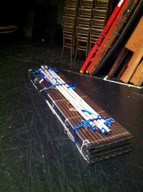
Here it is all packed up, I should weigh it for real but I'm guessing it's around 80 lbs total:
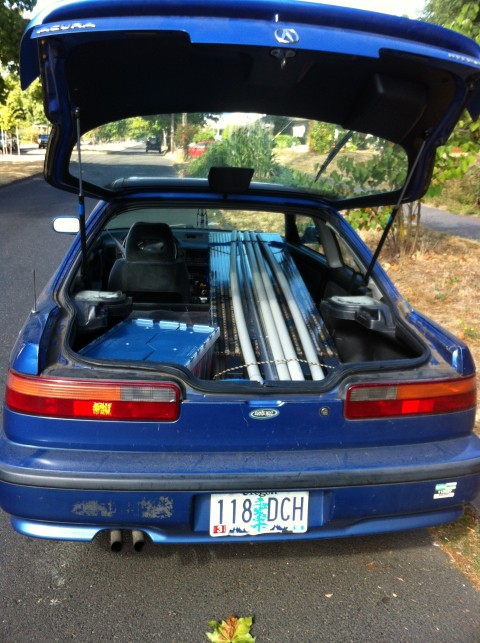
Look, it fits in my Acura:
All in all, it was a really fun and rewarding project, the band was great to work with, and everybody was really happy with the results. But, most importantly, we learned stuff.
If there's interest, I can go into more detail about the construction process - please leave comments below if there's more you want to know. I'm not really planning on doing a full step-by-step unless somebody wants to pay me to do it, but I'm more than happy to provide more info if anybody else wants to tackle this one.
(Rhino .3dm CAD file is zipped below)