Inspired by Laen's group PCB order and Ladyada's
breadboard power supply, I decided to try making one that runs from a single AA battery.
click
Read more for schematic and rambling about the design.....
 Larger schematic
 1280 pixels wide
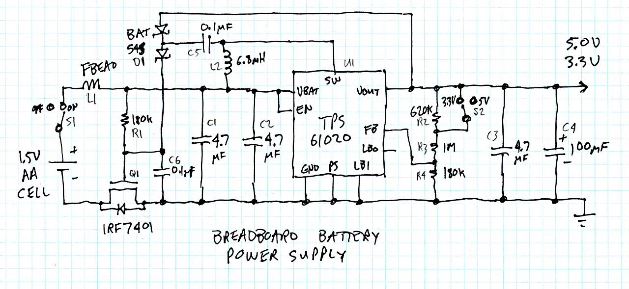
The TI
TPS61020 chip does all the heavy lifting. It's a pretty amazing chip.... I just hope it works as well as the datasheet says. TI claims it's 96% efficient (indeed it does use sync rectification), but I suspect that doesn't include copper and core losses in the inductor.
I included a MOSFET to (hopefully) protect against reverse polarity insertion of the battery. The funny capacitor and diodes thing attached to the inductor is pretty much right out of an example in the TPS61020 datasheet to create an unregulated voltage approximately double the output voltage. When you first attach the battery, the mosfet only turns on because of the battery voltage, but once the chip starts switching, the mosfet gate should be driven with at least 6 volts, which gets it to it's lowest on resistance. In theory, it should only be 0.022 ohms. With only one AA battery, there's no extra voltage to waste!
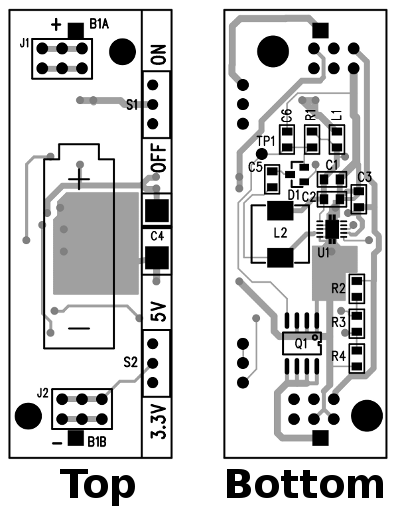
I wanted to keep this thing as small as possible, so nearly the entire top side is taken up by the AA battery holder. There's just a little exposed strip on the right side, for two little slide switches to turn it on/off, and to select 3.3 or 5 volts. I suppose I could have made it also adjustable like Ladyada's, but there wasn't room to place a pot without making the board quite a bit larger.